
6 Easily Overlooked Considerations in
CNC Part Design
Yes, we won't be discussing the common sense in CNC design, such as fillets, thin walls, or deep cavities. You're probably already well-versed in these principles. As experienced mechanical parts engineers, we’ve encountered many times design practices that can be enhanced to achieve efficient manufacturing, higher quality, and greater precision. By keeping in mind the following six easily overlooked considerations in CNC part design, you can unlock a world of possibilities and maximize the potential of your designs.
1.Ensure the Quality of Parts After Heat Treatment
When designing machined parts, it is necessary to consider the quality of subsequent processes such as heat treatment. Sharp edges and corners of parts can lead to stress concentration during quenching, resulting in cracking. Therefore, prior to quenching, the root of the shoulder of a heavy-duty stepped shaft should be designed with fillets, and chamfers should be provided on the shaft end and shoulder, as shown in Figure-1.
Additionally, uneven wall thickness of the part can easily cause deformation during heat treatment. It is advisable to add a process hole appropriately to achieve uniform wall thickness and prevent deformation during heat treatment.
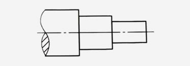
a) Original design
b) Optimized design
Figure-1: Shaft shoulder structure for easy heat treatment
2. Design for Easy Clamping
Clamping in CNC machining refers to the process of securely securing or holding a workpiece in place during machining operations to ensure stability and accuracy. Designing components for easy clamping means the parts can be accurately positioned and securely clamped, which improves machining efficiency, and ensures the part quality.

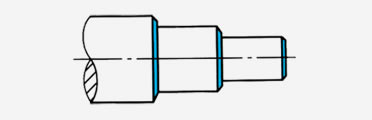
a) Original design b) Optimized design
Figure-2: Increasing clamping contact area
As shown in Figure-2, in original design, when the part is clamped on the three-jaw chuck, the part and the jaws have point contact, which does not securely hold the workpiece. In the optimized design, a cylindrical section is added to increase the contact area between the workpiece and the jaws, making clamping easier and improving clamping reliability.
3. Add Flanges or Process Holes to the Large Flat Workpiece
The large flat workpiece was initially challenging to clamp securely during the machining process. By adding flanges to the part, the clamping of the workpiece becomes more convenient and reliable. With the inclusion of flanges, screws and pressure plates can be used to securely hold the workpiece in place. Additionally, the incorporation of flanges facilitates the lifting and handling of the workpiece, making it easier to transport and manipulate.
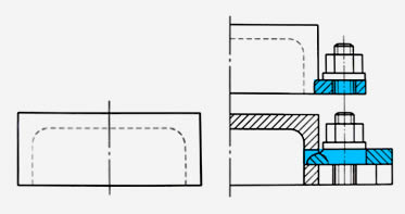
a) Original design b) Optimized design
Figure-3 Adding process flanges or process holes
4. Reduce the Tool Running Times

a) Original design

b) Optimized design
Figure-4 Reduce the tool running times
By reducing the times of machining tool passes, we can decrease the machining time and consequently reduce the machining costs. As shown in the original design of Figuture-4, when machining features with different heights, it was necessary to individually raise or lower the worktable, which increased the machining time. In the optimized design, several features with different heights are designed to have the same height. This allows machining all the features in a single tool pass, thus improving production efficiency and maintaining relative positional accuracy more easily.
5. Reduce Machining Area
Reducing the machining area can decrease machining time and subsequently reduce the cost of mechanical machining. As shown in Figure-5, in the original design, the bottom surface of the bearing component has a large machining area. In the improved design, the machining area was reduced through optimized design, resulting in a decrease in machining volume and tool consumption, improved machining efficiency, and reduced machining costs. Additionally, optimizing the component design by adding convex features or grooves can also help reduce the machining area.
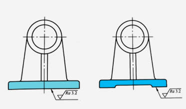
a) Original design b) Optimized design
Figure-5 Reduce machining area
6. Design for Ensuring Positional Accuracy
Surfaces with mutual positional accuracy requirements are preferably processed in a single clamping operation, which helps ensure the positional accuracy between the machining surfaces and reduces the number of clamping operations. In Figure-6, the inner and outer cylindrical surfaces require coaxiality accuracy. In the original design, the part needs to be clamped twice to machine the outer cylindrical surface and the inner hole separately, making it difficult to meet the coaxiality accuracy requirements.
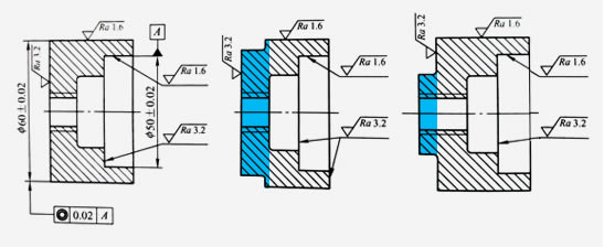
a) Original design b) Optimized design c) Optimized design
Figure-6: Design the part to ensure positional accuracy
In the improved design, by adding a raised platform structure, the inner and outer cylindrical surfaces can be machined in a single clamping operation, making it easier to meet the coaxiality requirements while also reducing the machining cost.
For additional help on your machining project, feel free to Contact Us. To get your next machining project started today, just upload a 3D CAD model and get an interactive quote within hours.