The holes, slots, and depressions in plastic parts are crucial features for proper assembly, ventilation, and even providing aesthetic value in some products. These features are formed by the core, the protruding part, of the mold. During the injection molding process, the core with excessive height or length bears higher impact force from the molten plastic, which can easily cause the displacement of the core and result in significant dimensional errors in hole features. Here’re eight design tips for injection molded holes to enhance the part quality and reduce the potential deformation.
1. Dimensional Rules for Hole Depths
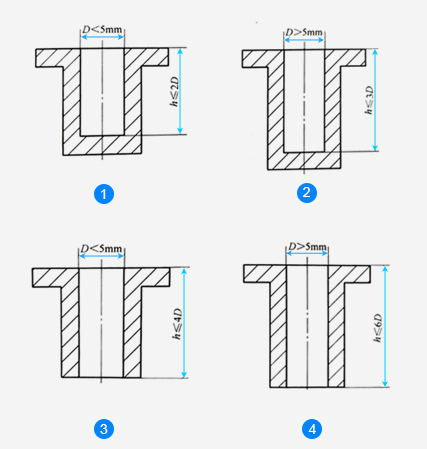
The common holes on plastic parts can be roughly divided into three types: blind holes, through holes, and stepped holes. Through holes are easier to manufacture than blind holes because the cores can be distributed on both sides of the molds, and the through hole depths can be appropriately increased. If the hole is too deep, the stepped hole method can be used instead in molding.
Dimensional rules:
1. For blind holes, if D<5mm, then h≤2D.
2. For blind holes, if D>5mm, then h≥3D.
3. For through holes, if D<5mm, then h≤4D.
4. For through holes, if D>5mm, then h≤6D.
2. Dimensional Rules for Blind Holes
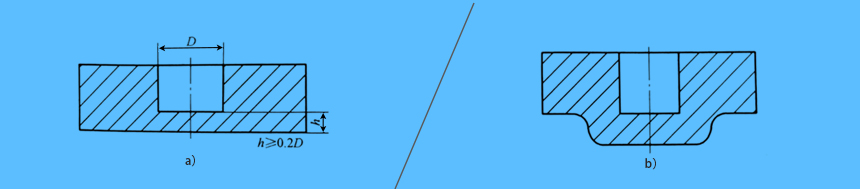
The thickness of the bottom of blind holes should be at least 0.2x the blind hole diameter. A thin bottom can result in a weak blind hole, even surface defects on the backside. If the bottom is too thin, its strength is sacrificed, and you may consider thickening the bottom to strengthen the blind holes as the figure b) shows.
a) The bottom height of blind holes should be at least 0.2x the blind hole diameter, i.e.: h≥0.2D.
b) Consider strengthening the bottom of blind holes as figure b) shows.
3. Dimensional Rules for Holes, and Space between Holes and Part Edge
It is recommended to maintain the space of at least 1.5x the diameter of the part hole or the wall thickness, whichever is greater, between holes and between holes and the part edge. In other words, s ≥ 1.5t or 1.5D should be followed.
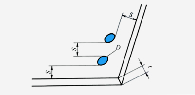
The dimensions for hole space, and the space between hole and part edge should follow s ≥ 1.5t or 1.5D.
4. Holes Should be Placed as Far Away from the Loaded Areas as Possible
Since the holes are created by removing material from the parts, the part strength is reduced. Therefore, the area around the holes (especially when there are many holes) is prone to welding marks, the strength of the parts will be further weakened. It is advisable to avoid placing too many holes in the loaded areas of the parts.
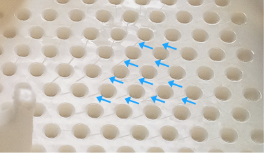
The welding marks are highlighted with blue arrows.
5. Add Boss Feature to the Hole Edge
To increase the strength of a hole and prevent it from deforming, a boss feature can be added around the edge of the hole. A similar design can also be used for long holes or slots that require increased strength. It is generally considered that at least 0.3-0.5mm of boss should be reserved to ensure the robust hole structure and to provide enough space for possible other elements or coatings.
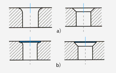
a) The original hole design is prone to deformation.
b) Add the boss to hole edge to strengthen the part.
6. Avoid Side Holes Perpendicular to the Parting Direction of the Mold
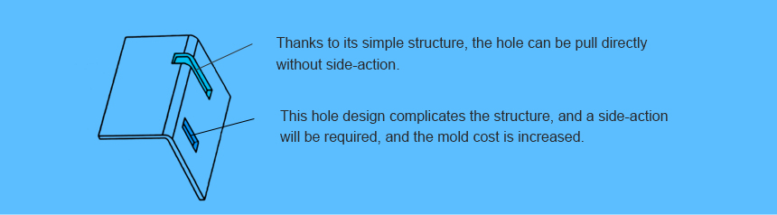
Try not to complex the mold structure when designing holes. To simplify the mold structure and reduce the cost of the mold, the design of side holes perpendicular to the parting direction should be avoided.
Side holes perpendicular to the parting direction of the part needs the extra side-actions (or side-pulls), which increases the complexity of the mold and leads to higher mold costs.
7. Avoid the Deep Holes that Impede the Flow of Molten Plastic
A deep hole refers to a long and narrow opening. The direction of the elongated hole should be consistent with the flow direction of the molten plastic to avoid being perpendicular to it, which would impede the flow of the plastic. If the direction of the elongated hole is perpendicular to the flow direction of the molten plastic, it may result in defects and non-uniformity in the final product.
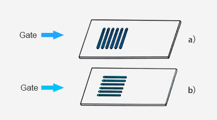
a) The hole direction is perpendicular to the flow direction.
b) The hole direction is consistent with the flow direction.
8. The Design of Vent Holes
Vent holes are often required in products, due to the need for heat dissipation. In general, when the vent hole is round, the mold core is cylindrical, which makes it easy to process and results in low mold costs. However, when the vent hole is hexagonal, it is more difficult to manufacture and does not necessarily provide better ventilation. Excessive vent hole design can cause a reduction in part strength, which can be addressed by increasing the strength of the part at the vent hole through adding ribs or bosses.
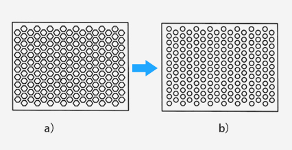
The round holes design is recommended, as it is easy to process, leading to low mold costs and even better ventilation.
As always, no single design tip can cover all injection molded issues. For additional help or get your injection molded project started,
Contact Us now.