
5 Mistakes to Avoid When
Designing Machined Parts
— Optimize Part Design for CNC Machining time and cost
Designing parts for CNC machining may seem straightforward—raw materials is removed from a solid block to create the desired shape. However, there are many ways your designs can encounter issues may arise from parts that are not designed with manufacturability in mind.
We conclude some of the most critical issues, that our engineering experts frequently meet in quote requests. Avoiding the issues will help you improve your part design, shorten lead time, and even perhaps save some costs along the way.
Avoid the Sharp Internal Corners
Not all features are achievable, a typical example is an internal angle of 90°. See Figure-1. This is because all current CNC milling tools have a cylindrical shape, which creates a rounded edge instead of a straight or sharp angle when cutting along the edges of the machined cavity. If a straight angle must be retained, the usual approach is to use EDM (electrical discharge machining), which is a more expensive manufacturing process than CNC machining.
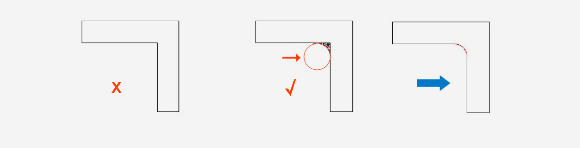
Figure-1 Original Design
Optimal Design
Tools
Avoid Designing Thin, Tall Walls
When designing for CNC machining, it is important to avoid designing excessively thin or tall walls. While thin walls may be necessary for certain projects, it is important to note that studies have shown that wall thickness is proportional to the stiffness of the material, which can impact the achievable accuracy due to vibrations during machining. The standard minimum thickness for walls is 0.8 mm for metals and 1.5 mm for plastics, see Figure-2. Meanwhile, tall walls may result in issues such as undesirable surfaces, difficulty in meeting part tolerances, and the risk of chipping, bending, or breaking. A good rule of thumb for walls is a width-to-height ratio of 3:1.
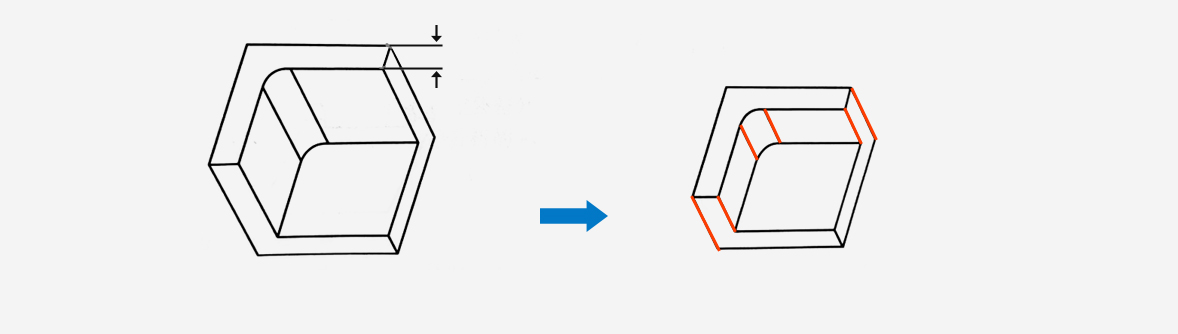
Figure-2 Original Design
Optimal Design
Wall Thickness
For Metals:
WT>0.8mm
For Plastics:
WT>1.5mm
Avoid Parts with Unnecessary Tight Tolerances
Although CNC machining can tolerate some of the tightest tolerances in manufacturing process, it doesn't mean that every part needs to have the strictest tolerances. In fact, using tight tolerances only when absolutely necessary can greatly reduce costs. As precision requirements increase, more precision manufacturing processes are needed, leading to lower production efficiency and higher costs.
But sometimes, the flawless assembly can be achieved through creating reasonable gaps, simplifying assembly relationships, and using positioning features. In addition, it is also important to maintain same tolerancing as this would reduce machining time. See an example in Figure-3.
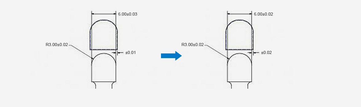
Figure-3 Original Design
Optimal Design
Avoid the Small and Deep Holes, and the Curved Holes
The small, deep holes should be avoided as they can cause drill breakage and make chip removal difficult. The ratio of hole depth to diameter should not exceed 3, and one method to avoid deep holes is to use stepped holes. Blind holes require an additional 25% of hole depth for chip storage. Additionally, the curved holes cannot be machined using CNC methods. However, if this feature is required in your design, Electrical Discharge Machining (EDM) can be used to achieve, with the raised production cost along the way.
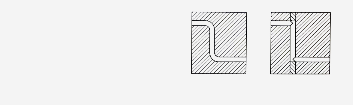
Figure-4 Avoid the curved holes
Avoid the Deep Cavity
There is a certain proportional limit to the machining depth of CNC cutting tools, and the best machining performance is achieved when the cavity depth is 2-3 times the diameter of the tool. Of course, it is possible to machine deeper cavities, up to a maximum of 4 times the tool diameter, but this will increase costs, especially when using multi-axis CNC machine tools. For example, a milling cutter with a diameter of 12mm can safely machine a cavity with a maximum depth of 25mm, not exceeding 48mm. See Figure-5.
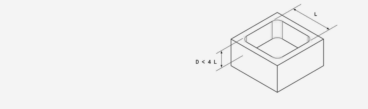
Figure-5 Limit the depth of cavity to 4 times their length
Summing it Up
Of course, no one single design tip can address every practical design issues. For additional assistance, feel free to CONTACT US, and you can get the in-depth and customized design analysis. To get your next design project started today, simply Upload a 3D CAD model now.